This motor driver shield and its corresponding Arduino library make it easy to control a pair of bidirectional, brushed DC motors with an Arduino or compatible board, such as the A-Star 32U4 Prime. The board features Allegro’s A4990 dual H-bridge motor driver IC, which operates from 6 V to 32 V. It can deliver a continuous 0.65 A to each motor channel, and the current control feature of the A4990 limits the peak motor current to about 0.9 A per channel with the onboard sense resistors, making this shield well suited for low-current, high-voltage motors.
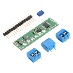
The shield ships fully populated with its SMD components, including the A4990 driver and a FET for reverse battery protection; header pins for interfacing with an Arduino and terminal blocks for connecting motors and power are included but are not soldered in (see the Assembly with included hardware section below).
The shield uses digital pins 6, 7, 8, 9, and 10 for its diagnostic and control lines. It should be compatible with any board that has a standard Arduino pin arrangement and the ability to generate PWM signals on pins 9 and 10. Compatible control boards include:
- A-Star 32U4 Prime
- Arduino Uno
- Arduino Leonardo
- Arduino Due
- Arduino Mega 2560
This shield is intended to provide a low-cost, basic motor driver option for Arduinos, so it is much smaller than typical Arduino shields and does not include pass-through, stackable headers. For higher-power drivers with more configuration options, see our larger MC33926 and VNH5019 motor driver shields.
For a lower-voltage, higher-current alternative to this shield, please consider the DRV8835 dual motor driver shield. We also have a smaller A4990 carrier for those using something other than an Arduino or with tighter space constraints.
Features
- Dual-H-bridge motor driver: can drive two DC motors or one bipolar stepper motor
- Motor supply voltage: 6 V to 32 V
- Logic supply voltage 2.5 V to 5.5 V
- Output current: 0.65 A continuous per motor
- Current control limits peak current to 0.9 A per motor
- Can work with ultrasonic (> 20 kHz) PWM frequencies, which allows for quieter motor operation
- Shield can optionally power the Arduino base directly when motor supply voltage is suitable
- Arduino library makes it easy to get started using this board as a motor driver shield
- Robust:
- Reverse-voltage protection on the motor power supply
- Can survive input voltages up to 40 V
- Under-voltage and over-voltage protection
- Over-temperature protection
- Short-to-supply, short-to-ground, and shorted-load protection on the motor outputs
Assembly with included hardware
Before the shield can be plugged into your Arduino, header pins must be mounted to the bottom of the board (the side with all of the surface-mount components) by soldering them into the appropriate holes. The shield ships with a 15-pin 0.1? straight breakaway male header strip that can be broken into smaller pieces and used for this purpose. Four holes along the left side of the board (VCC, GND, GND, and AVIN) and all five holes along the right side of the board (digital pins 6 – 10) should be assembled with male header pins so that the shield will make the appropriate connections to the Arduino. Once assembled, one easy way to ensure that you are plugging the shield properly into the Arduino is to align the gap between pins 7 and 8 on the shield with the gap between pins 7 and 8 on the Arduino’s female headers.
If you want the option of powering the Arduino from the shield, you can solder two male header pins to the lower-left corner of the board (in the silkscreen box labeled “VOUT”). These pins should point up, away from the Arduino. If you then place the included blue shorting block across these pins (as shown in the above assembled picture), reverse-protected shield power will power the Arduino through it’s VIN pin. See the Using the shield section below for more information on this, including some important warnings.
Three 2-pin, 5 mm terminal blocks are included for making easy motor and power connections to the shield once they have been slid together and soldered to the six large through-holes. Alternatively, you can solder 0.1? male header pins to the smaller through-holes above the terminal block holes, or you can just solder wires directly to the shield.
An Arduino is not included.